Walk into any large factory in India and the noise hits you before anything else does. Compressors whirring, generators rumbling, machinery hammering away — it is relentless. And for the workers who spend eight to twelve hours in that environment every day, it is not just uncomfortable. It is genuinely dangerous.
That is where acoustic enclosure design guidelines come in. Not as a box to tick or a document to file away. As a real, practical framework that tells engineers exactly how to build a structure around a noise source so that the sound stays where it belongs — inside.
This article covers the whole subject. The physics, the materials, the ventilation problem, the step-by-step process, common mistakes, and the Indian regulatory context. Whether you are specifying an enclosure for the first time or trying to understand why the one you already have is not performing, this is the guide you need.
📞 Call +91 9891320678 | ✉️ Sales@ecotone.in
1. What Is an Acoustic Enclosure — and Why Should You Care?
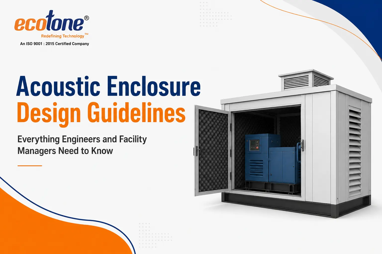
An acoustic enclosure is, at its most basic, a box that goes around a noisy machine. But that description does not do it justice. A well-designed enclosure is a precision-engineered system. Every wall, every joint, every ventilation opening, every access panel — all of it has been calculated to block, absorb, or redirect sound energy.
The machines that typically need them include diesel generators, industrial compressors, CNC equipment, pumps, turbines, blowers, and test dynamometers. What they have in common is that they generate noise levels well above what humans or regulations can tolerate in the surrounding area.
Acoustic enclosure design guidelines exist because without them, people guess. They buy panels that look thick enough, bolt them together, and wonder why the noise level barely dropped. The guidelines take the guesswork out. They define the inputs, the calculations, and the verification process — so the outcome is predictable before a single panel is fabricated.
A well-designed acoustic enclosure does not just reduce noise. It controls it — at every frequency, through every surface, around every penetration.
2. The Physics Behind Noise Containment
You cannot design an enclosure without understanding what sound actually does when it hits a wall. Sound is pressure — waves of alternating compression and rarefaction moving through the air. When those waves reach a solid surface, three things happen simultaneously: some energy is reflected, some is absorbed within the material, and some is transmitted through to the other side.
The ratio of these three outcomes depends on the wall’s physical properties. This is why acoustic enclosure design guidelines always begin with understanding the source noise — its level and, critically, its frequency content.
Why Frequency Matters More Than Most People Realise
Low-frequency noise — the deep thud of a diesel engine, the bass rumble of a large compressor — is far harder to control than mid or high-frequency sound. Lower frequencies have longer wavelengths and more energy, and they pass through most standard wall constructions with relative ease.
This is one of the most common failure modes in enclosure projects. The designer specifies a wall that achieves excellent sound reduction at 500 Hz and above, but at 125 Hz — where the engine is loudest — the attenuation is maybe a third of what was expected. The enclosure is technically built to spec, but the dominant problem frequencies have not been addressed.
Good acoustic enclosure design guidelines force you to work in octave bands, not just with a single dB(A) figure. That single number hides too much.
Mass Law: The Starting Point for Wall Design
The mass law is the foundation of panel design. It states that for every doubling of surface mass, sound transmission loss increases by approximately 6 dB. In practice, this means heavier panels block more sound — but only up to a point. Beyond the mass law, coincidence effects and stiffness resonances create dips in performance at specific frequencies. This is why a double-leaf panel with a decoupled air cavity almost always outperforms a single panel of the same total weight.
From DG sets to anechoic chambers — engineered for your exact noise problem.
Visit Ecotone Systems →
3. The Four Non-Negotiables in Acoustic Enclosure Design Guidelines
3.1 Sound Transmission Loss (STL)
Sound Transmission Loss is the headline spec — the number that tells you how many decibels the wall knocks off the incident sound. It is measured in a laboratory under controlled conditions, and it varies with frequency. When specifying panels for an enclosure, you should always be looking at the STL curve across the full octave-band range, not just a single-number summary.
The required STL at each frequency is derived from subtracting the target noise level at the receiver from the source noise level. Add a safety margin of at least 5 dB, because real-world installations always have flanking paths and other losses that eat into the theoretical performance.
3.2 Internal Absorption — Controlling Reverberation
Here is something that surprises many first-time enclosure specifiers: without internal absorption treatment, a sealed enclosure can actually perform worse than an open space. The sound bounces around inside, building up a reverberant field that pushes back against the wall and increases the effective transmission.
Internal absorption — mineral wool, glass wool, or acoustic-grade open-cell foam — converts sound energy into heat through friction. It needs to be applied to all internal surfaces, and the facing (usually perforated steel sheet) needs to be acoustically transparent, meaning the perforation ratio has to be high enough not to block the absorption.
3.3 Flanking: The Problem That Sinks Otherwise Good Enclosures
Flanking is the term for sound that bypasses the main barrier by taking indirect routes. It is, without question, the most common reason that installed enclosures fail to meet their design targets in the field.
The routes that flanking typically exploits include rigid structural connections between the machine and the enclosure floor, pipes and ducts that pass through the enclosure walls without flexible connectors, cable entries that are not properly sealed, and gaps at door frames that are negligible-looking but acoustically significant.
Addressing flanking is not glamorous work, but it is essential. The acoustic enclosure design guidelines that experienced engineers follow treat every single penetration as a potential problem until proven otherwise.
- Anti-vibration mounts under the machine base — mandatory, not optional
- Flexible connectors on all pipework and ductwork at the enclosure wall
- Sealed cable glands on all electrical entries
- Acoustic doors with drop seals, perimeter compression seals, or magnetic seals
- Labyrinthine or parallel-baffle silencers on all ventilation openings
3.4 Ventilation: The Acoustic Engineer’s Hardest Problem
Every enclosed machine generates heat, and heat has to go somewhere. If you seal the enclosure perfectly, the machine overheats within minutes. If you open it up for ventilation, the sound leaks out. There is no magic solution — only careful engineering.
Acoustic silencers — also called attenuators or baffles — are lined duct sections where the air can flow freely but the sound has to navigate a path covered in absorptive material. They work well, but they add pressure drop to the ventilation system, which means larger fans, higher energy consumption, and more noise from the fans themselves.
Getting the ventilation design right requires calculating the heat load properly, sizing the airflow, selecting silencers that hit the required insertion loss across the problem frequencies, and verifying that the fan noise does not introduce a new noise problem of its own.
Our engineers handle everything — from noise survey to final commissioning test.
Contact Us →
4. Material Selection — What the Guidelines Actually Recommend
One of the things that trips up procurement teams is treating acoustic enclosure panels like ordinary construction materials. They are not. The right choice depends on the frequency profile of the noise, the operating temperature inside the enclosure, the maintenance access requirements, the expected service life, and how much space is available.
| Material | Primary Function | Best For | Performance |
|---|---|---|---|
| Double-leaf steel panels | Sound blocking (STL) | Generators, compressors | 30–45 dB(A) |
| Mineral wool / Rockwool | Internal absorption (NRC) | All enclosure interiors | NRC 0.85–0.95 |
| Glasswool infill | Cavity absorption | Panel air gaps | High mid/high freq |
| Mass-loaded vinyl (MLV) | Flexible STL barrier | Wrapping, sealing | 20–35 dB(A) |
| Perforated steel facing | Acoustic protection layer | Over absorptive infill | Transparent to sound |
| Anti-vibration mounts | Structure-borne isolation | Machine-to-floor connection | 15–30 dB vibration |
One material combination that Ecotone Systems has deployed across dozens of projects in India is a 1.6mm outer steel skin, 50–100mm Rockwool fill, and a perforated inner face panel. For applications where low-frequency attenuation is the priority — large DG sets, for instance — the outer panel is upgraded to 2mm, and the cavity depth is increased to push the mass-spring-mass resonance down to a frequency below the problem range.
5. A Practical Step-by-Step Design Process
Understanding the principles is one thing. Knowing how to actually go from a noisy machine to a completed, tested enclosure is another. Here is how the process looks in practice, following established acoustic enclosure design guidelines.
Step 1 — Measure First, Design Later
This step gets skipped more often than it should. The temptation is to go straight to a standard solution — ‘it is a 500 kVA generator, so we will use our standard generator enclosure.’ That works sometimes. But if the installation has an unusual layout, if the nearest receiver is much closer than typical, or if there is a specific low-frequency problem, the standard solution will underperform.
What you need is an octave-band sound power level measurement of the source. Not just an overall dB(A) level. The full spectrum, from 63 Hz to 8 kHz, at a standard measurement distance.
Step 2 — Define the Target
Once you know where you are starting from, you need to know where you need to get to. The target noise level at the receiver point might come from Indian regulatory limits, from an employer’s occupational health policy, from a neighbour’s complaint, or from a client specification. Subtract that target from your measured source level, add your safety margin, and you have the required insertion loss, octave band by octave band.
Step 3 — Choose the Enclosure Configuration
Full enclosure, partial enclosure, or close-fitting enclosure — each has its place. Full enclosures (all six sides) give the highest attenuation but restrict access and create the most challenging ventilation problem. Partial enclosures trade some acoustic performance for easier maintenance access. Close-fitting enclosures wrap tightly around the machine and work well when space is limited, but they require particularly careful attention to flanking through the structure.
Step 4 — Design the Panel Build-Up
Using the STL requirements derived in Step 2, select a panel construction that meets or exceeds the required loss at every octave band. This is where the mass law calculations, manufacturer test data, and sometimes finite element modelling come together. For standard panels, published third-party test data is available and should be used in preference to manufacturer claims alone.
Step 5 — Design the Ventilation System
Calculate the heat load. Determine the required air flow rate. Select inlet and exhaust silencers that achieve the required insertion loss. Check the pressure drop. Specify the fans. Verify that the fan noise does not breach the enclosure’s performance target. This step alone can take more time than all the others combined on a complex project.
Step 6 — Detail Every Penetration
Every pipe, cable, duct, door, and service opening through the enclosure wall needs to be specified in detail. Flexible connectors, cable gland types and materials, door seal specifications, threshold seal types — all of it. This is the step that separates enclosures that hit their targets from those that do not.
Step 7 — Build, Install, Measure
After fabrication and installation, conduct a post-commissioning noise survey using the same measurement methodology as the initial survey. Compare the achieved insertion loss against the design target at each octave band. Document everything. If any bands fall short, identify the flanking path and remediate.
Ecotone Systems — Plot No-08, Ecotech 12, Greater Noida, UP | Mon–Sat: 9 AM–6 PM
+91 9891320678 | Sales@ecotone.in
6. Indian Regulations You Cannot Ignore
In India, noise control is not just good engineering practice — it is a legal obligation. The regulatory framework has teeth, and companies that ignore it face penalties, production stoppages, and in serious cases, forced closure.
| Standard / Rule | What It Governs | Key Limit / Requirement |
|---|---|---|
| Noise Pollution Rules, 2000 | Ambient noise by zone | Industrial: 75 dB(A) day, 70 night |
| Environment Protection Act, 1986 | Overall noise framework | Central Govt empowered to set limits |
| Factories Act, 1948 | Worker noise exposure | Occupational exposure limits |
| IS 9901 | Machinery noise measurement | Indian std for source measurement |
| ISO 15667 | Enclosure design & testing | International design guidelines |
| ISO 11546 | Insertion loss measurement | Field verification methodology |
The Noise Pollution (Regulation and Control) Rules 2000 are the most directly relevant for most industrial facilities. They set permissible limits at the boundary of the facility, which means the enclosure design has to account not just for the immediate machine environment but for the propagation of sound from the source to the boundary.
For large installations near residential areas — which describes a significant proportion of industrial estates in India’s rapidly expanding cities — this can mean achieving insertion losses of 40 dB(A) or more. That is only possible with a properly engineered full enclosure, not with barriers or partial treatments.
7. The Most Common Mistakes — and How to Avoid Every One
Mistake 1: Treating Low Frequencies as Someone Else’s Problem
Specifying a wall that performs well above 250 Hz while ignoring what happens at 63 Hz and 125 Hz is one of the most persistent mistakes in the industry. The dominant noise from most industrial prime movers is in the low frequencies. An enclosure that cannot address that is, at best, a partial solution.
The fix is straightforward: work in octave bands from the beginning, identify the dominant problem frequencies in your measured source spectrum, and specify a panel construction that achieves the required STL at those frequencies specifically.
Mistake 2: Bolting the Machine to the Enclosure Structure
This is a surprisingly common detail error, especially on smaller projects where a separate structural base is considered an unnecessary cost. When the machine is rigidly connected to the enclosure, its vibration travels directly into the walls and radiates outward. The airborne noise reduction of the enclosure is largely negated by the structure-borne path.
Anti-vibration mounts are not expensive relative to the cost of the enclosure. They are always worth including.
Mistake 3: Skipping the Post-Commissioning Survey
Some clients view the post-commissioning noise survey as an optional add-on. It is not. It is the only way to verify that the enclosure is performing as designed. Without it, you are relying on faith rather than evidence — and if a noise complaint arrives later, you have no documented basis to demonstrate compliance.
Mistake 4: Ignoring Door and Access Panel Performance
An acoustic door rated to 35 dB(A) insertion loss, when the surrounding wall achieves 42 dB(A), is the limiting element. The overall performance of the enclosure is capped by the weakest element. Doors and access panels need to be specified to the same performance level as the wall panels, and their seals need to be maintained over the life of the installation.
Mistake 5: Buying on Price Alone
The cheapest enclosure is rarely the cheapest solution. An underperforming enclosure has to be modified, retrofitted with additional treatment, or sometimes demolished and replaced. The cost of getting the design right upfront is a fraction of the cost of fixing it afterwards — especially once you account for the productivity impact of ongoing noise problems and the regulatory risk of being in breach.
We audit existing enclosures and redesign for full compliance.
Sales@ecotone.in
8. Enclosure Types and Where They Are Used
Not every noise source needs the same solution. One of the practical things that good acoustic enclosure design guidelines do is help you match the enclosure type to the specific application and performance requirement.
| Enclosure Type | Typical Application | Insertion Loss Range |
|---|---|---|
| Full Generator / DG Enclosure | Power plants, hospitals, infrastructure sites | 25–45 dB(A) |
| Engine & Dyno Test Cell | Automotive R&D, powertrain development labs | 30–55 dB(A) |
| Compressor Enclosure | Oil & gas, process industry, manufacturing | 20–40 dB(A) |
| Anechoic / Semi-Anechoic Chamber | NVH testing, product acoustic development | 50 dB(A)+ |
| Operator Pulpit Enclosure | Rolling mills, steel plants, cement facilities | 25–40 dB(A) |
| Transformer Acoustic Enclosure | Power substations, electrical distribution | 15–30 dB(A) |
| Cooling Tower / Chiller Enclosure | HVAC plant, industrial cooling systems | 10–25 dB(A) |
Each of these applications has its own specific challenges. A generator enclosure has to handle exhaust heat and provide access for fuel fill and servicing. A dyno test cell has to accommodate engine cooling water and exhaust ducting. An anechoic chamber has to achieve deep wedge performance right down to 63 Hz. The design guidelines provide the framework, but the engineering detail is always application-specific.
📞 +91 9810319823 | 💬 WhatsApp: +91 9891320678 | Sales Team: +91 99115554819. Specifying for Specific Environments
Hotels, Commercial Buildings, and Hospitals
These environments have stringent noise requirements driven by occupant comfort and, in the case of hospitals, patient recovery. DG sets and HVAC plant are the primary noise sources, and the enclosures around them typically need to achieve ambient levels of 35–45 dB(A) in adjacent occupied spaces. The key challenge is often working within architectural constraints — the plant room may have limited floor area, low ceiling heights, and shared walls with occupied spaces that cannot be used as structural supports for the enclosure.
Manufacturing and Heavy Industry
Here the drivers are usually regulatory compliance at the facility boundary and occupational noise exposure for workers. The noise sources are varied — from high-frequency cutting tool noise to low-frequency press and forging noise — and the enclosures have to accommodate heavy maintenance access, process connections, and in many cases, robotic or automated material handling systems that pass through the enclosure boundary.
Power Generation and Utilities
Large generating sets, transformers, and pumping stations are often located in or near residential areas, particularly in Indian cities where industrial and residential zones are not always well separated. The Noise Pollution Rules 2000 limits at residential boundaries — 55 dB(A) during the day, 45 dB(A) at night — can require insertion losses of 30–40 dB(A) or more, which calls for well-engineered full enclosures with careful attention to all the flanking paths.
10. What to Look for in an Acoustic Engineering Partner
If you are procuring an acoustic enclosure for the first time, the number of suppliers who will present themselves as qualified can be bewildering. Some of them are panel fabricators with no acoustic engineering capability. Others have the engineering knowledge but lack the manufacturing and installation experience. A few have both.
The things worth asking about are: Do they conduct their own pre-design noise surveys? Do they have in-house acoustic modelling capability? Can they show you third-party tested STL data for their panel systems? Do they perform post-commissioning noise verification and provide documented results? Are they familiar with ISO 15667 and ISO 11546 methodology?
Ecotone Systems has been operating at the intersection of acoustic engineering and industrial manufacturing for decades. The company’s project portfolio spans DG enclosures, NVH test chambers, reverberation facilities, rolling mill pulpits, semi-anechoic chambers, and transformer noise control installations — across clients ranging from large PSUs to multinational manufacturers. That breadth of experience matters, because the challenges in a steel plant compressor room are genuinely different from those in a hospital generator installation, and both are different from a test cell for powertrain development.
Good acoustic engineering is not about applying a standard solution. It is about understanding the specific problem, designing to the specific target, and verifying that the solution works before the job is closed out.
Get expert guidance from survey to sign-off.
📞 +91 9891320678 | ✉️ Sales@ecotone.in
Conclusion
Acoustic enclosure design guidelines exist because noise control is an engineering discipline, not a shopping exercise. The physics of sound transmission, the requirements of internal absorption, the challenge of ventilation, the invisible threat of flanking paths — none of these can be handled by intuition or by buying the thickest-looking panel in a catalogue.
Getting an enclosure right means measuring the source, defining the target, designing systematically across octave bands, detailing every penetration, and verifying the result. It means choosing materials for the right reasons, not the obvious ones. It means treating low frequencies with the seriousness they deserve.
In India’s regulatory environment — and with worker health standards that are finally being enforced more consistently — the cost of getting this wrong is rising. The cost of getting it right, with a partner who has the engineering depth to deliver it, is almost always a fraction of what a failed solution ends up costing in remediation, lost productivity, and regulatory risk.
If your facility has a noise problem, the next step is a conversation — not a catalogue.
Contact Ecotone Systems — Your Industrial Acoustic Engineering Partner
📍 Greater Noida, UP | 🕘 Mon–Sat 9AM–6PM
✉️ Sales@ecotone.in |
📞 +91 9891320678 |
🌐 www.ecotone.in


